Povception
This is a rehosting of a blog originally on www.rs-online.com where our team won a £1,500 prize for the below project. As it’s now been taken offline I’m preserving it here!
We also won a single desk calendar to share between 3 people at our employer
This project was created by a three-man team comprising of two hardware engineers and a software engineer. From the very beginning, we knew we wanted to do something unique and challenging for a Christmas competition. The idea of trying to get a persistence of vision globe inside another was proposed and after finding no existing implementations of the idea we began the project.
We already had some of the necessary materials available when we started the project, including an STM32F469i discovery board and motors borrowed from a quadcopter. We also had tools and software available to aid in the design and manufacture of the POVception. These included a laser cutter, metal lathe, 3D printers, MathWorks Simulink, SolidWorks and a Root3 CNC for milling wood and etching a PCB.
When designing the mechanical assembly, the need for a front area where the user would interact and have an unobstructed view of the globes was required. The globes could not be mounted from the bottom alone due to the size. Therefore, transparent frames would be at the back and curve up and mount to the top of the globes to keep it stable and allow people to still view it from the back. Another initial decision was for the rings to rotate in opposite directions meaning two motors were required. There wasn’t an engineering reason for this choice, we felt that it would look impressive when it started spinning up with the LEDs on.
With the assembly modelled we started with milling the baseboards and the rings out of 18mm thick softwood plywood. We decided to paint these dark grey to accentuate the lights. We designed the mounts for the boards, motors and power supply for 3D printing and printed them in ABS using 1.75mm RS Pro filament. Red was chosen to keep with the Christmas theme and add a nice accent colour to the finished design. For the transparent frames, we laser cut 3mm acrylic using two arms for each frame for some added rigidity. Mild steel was used for all the metal work on the project. This included the axles mounted to the rings and stand-offs for the two baseboards that sandwiched the electronics. To allow the inner axle to nicely pass through the outer a metal lathe was used to change the bore. For the stand-offs, the lathe was used to cut the rods to size and add a thread to them.
The final part of the assembly was the two game controllers, each one would have a single joystick to enable the users to play basic games like Pong. To keep things simple and save time we utilised one of the AdaFruit 2 axis thumb joystick breakout boards and 3D printed a case for it we found on Thingiverse. Two existing cables with DE-9 connectors were used with one end of the cable removed and the wires soldered to the breakout board and the other end remaining intact to plug into the POVception.
Initially, when thinking about the software, we had concerns with latency and resolution of the globes. The LED density of the LED strips determines the vertical resolution and the speed the LEDs can be changed combined with the motor speed determines the horizontal resolution. For the LED strip solution, we initially investigated using AdaFruit NeoPixel strips, they were very affordable but had some flaws. Namely, the strips weren’t clocked and had strict timing requirements. Because of this, part of the feasibility was whether the timing could be met with enough slack to perform other software tasks. If timing wasn’t met the image would end up corrupted and there would be no guarantees about what was displayed. Another issue with the NeoPixels was the spacing between the LEDs would restrict the vertical resolution.
After some experimentation, the NeoPixels were found unsuitable in terms of throughput, and the SPI driven DotStar LED strips were chosen instead. The DotStar LED strips had an LED density of 144 LEDs per metre and as they were driven by SPI the software could asynchronously drive them via DMA transfers. Looking online we could find no upper limit to the clock speed for the DotStars and after experimentation found they could be driven at the SPIs maximum speed of 10MHz with no issue.
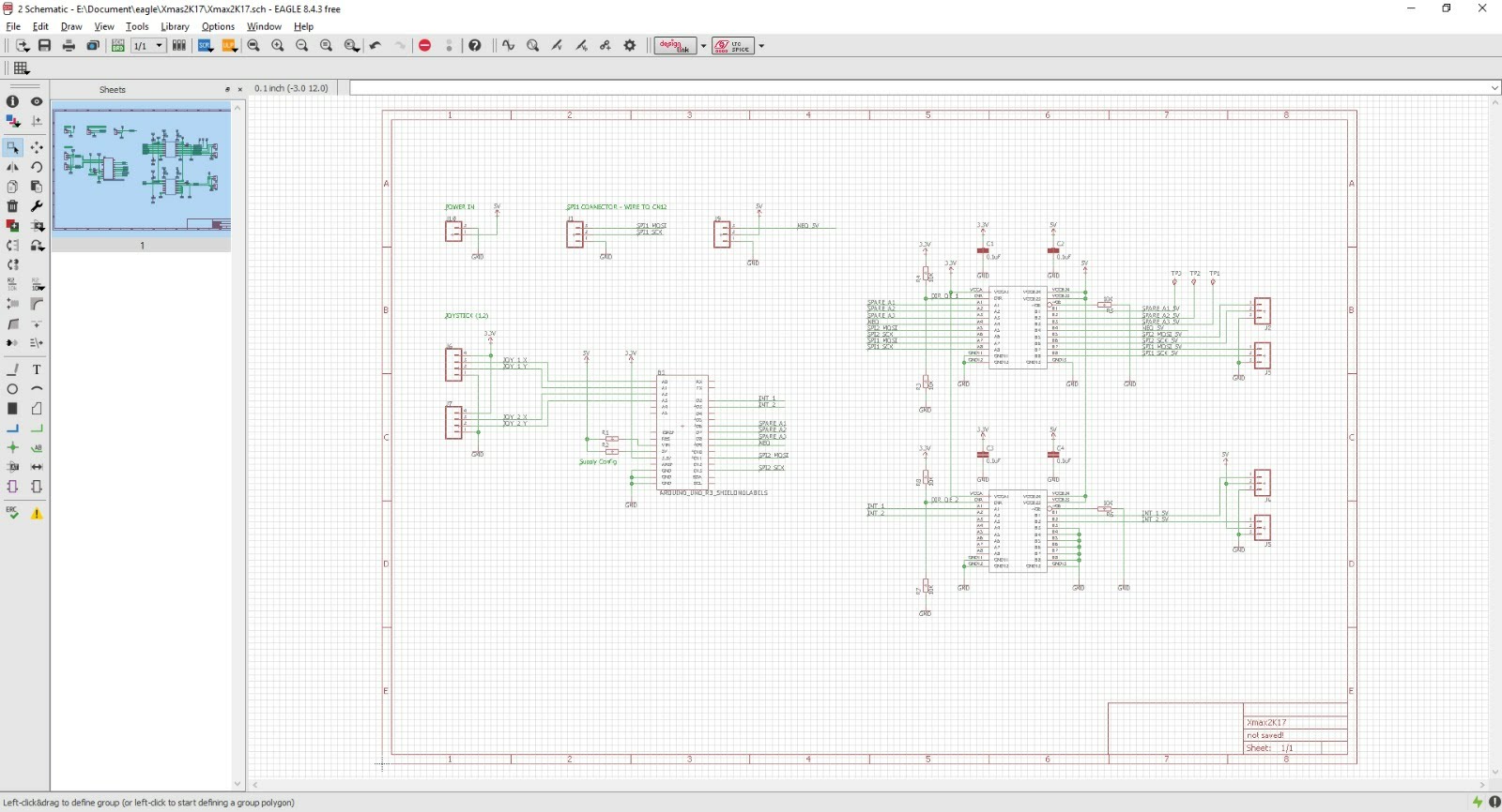
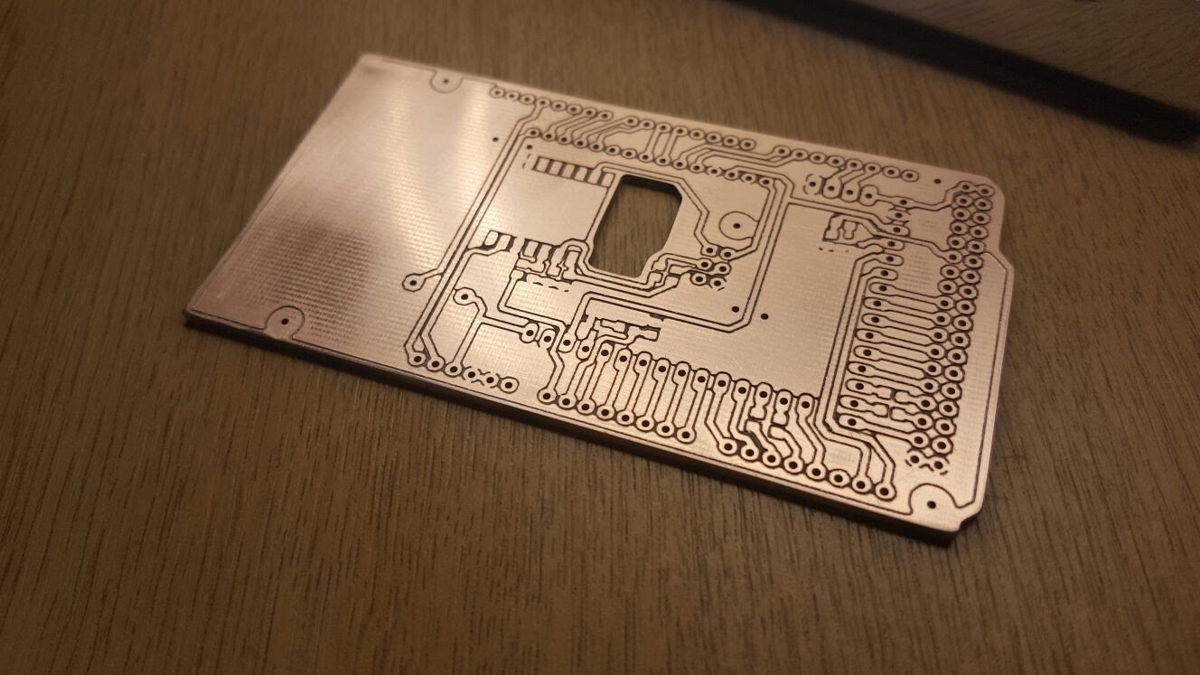
Both sides of each ring were also rendered and with only two SPI lines on the board we had to run the strips from the bottom of one ring going upwards then from the top of the opposite face running down. The DotStar SPI also ran at 5V compared to the STM32 running at 3.3V, so to prevent signal integrity issues an additional PCB was designed and etched to drive the LEDs as well as provide power to the motors.
On the software side, it was important the microcontroller didn’t spend time on blocking calls. The STM32 was responsible for: motor control for two motors, updating the display frames and rendering the two rings. Additionally, the discovery board had a touchscreen display featuring a simple GUI which had to be polled and updated accordingly. The majority of the code was done in C++ with the STM32 HAL and some ARM Mbed API functions used for interacting with the hardware.
MathWorks Simulink was utilised in the creation of the project. Given previous experience with Simulink in control systems, it was decided that it would be used for the motor control with the main C++ code base providing an interface between Simulink and the hardware. Using Simulink for control is a natural fit, however, integrating the generated code into a project involved reading the code to find the names for functions and structs you need to use. It would have been preferable and easier to write the code in C++ like the rest of the project – but then we wouldn’t have met all the requirements.
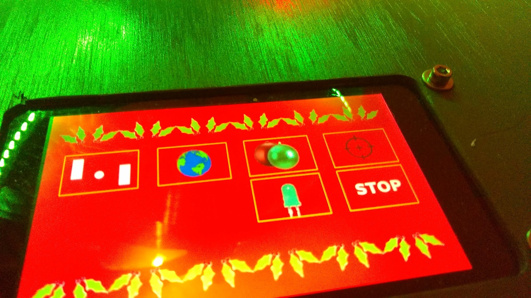
With the hardware and assembly done and software being integrated and refined in the final week some interesting traits were observed. When tracking which column was being rendered initially a modulus operator was used to ensure the index never went out of bounds. However, modulus is quite a slow operator so this would cause the last column to appear wider than the others and cause the display to jitter left and right. Replacing the modulus with an if statement to check the bounds and a subtract to move back into the range removed this effect. Additionally, adding new applications and icons for them in the GUI took up a lot of flash memory. The touchscreen HAL library supports bitmaps but only if they were stored in flash, with the POVception finished around 90% of the flash memory was being used by a mixture of code and resources.
The finished POVception had the following applications:
- Pong – the most important a classic Pong game. Pong on the inner ring, snowfall effect on outer
- Baubles – show a bauble pattern on both rings
- Calibration – use the joysticks and set the first column of the displays
- Globe – showed the globe on the inner ring with the snowfall effect on the outer ring
Of course, no project is ever perfect and there are some obvious things we would have changed and improved – had we had time. The first thing that comes to mind is that the HAL library for the touchscreen display only supported one landscape orientation. We didn’t realise this until after it was fitted and I had to flip all the bitmaps 180 degrees and remove any text printed to the screen. Also, there were some sporadic software bugs that were discovered for the first time on the demonstration day. In terms of the physical side, the DotStar strips got very hot and began to slightly peel off so better thermal management or a better adhesive would have improved the design.
Overall, the project was a success and the team was awarded an innovation prize. We’re all proud of what we managed to achieve in such a small amount of time and the project met all its aims. The project is largely open-source with the code currently available on GitHub (link at the end), eventually, the mechanical and hardware designs will also be uploaded to either GitHub or Thingiverse.
Here’s the code link
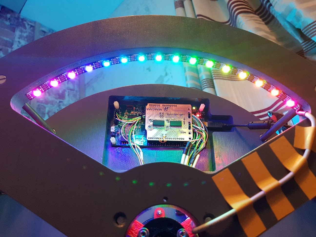
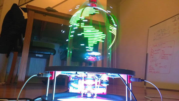
Here’s the finished project in action